LED Remote Controller

Introduction
The overall circuit is to replicate a simple remote that once one button is pressed a LED should light up and when another button is pressed the other LED should light up. This sounds like a simple task but “wireless” is the key point of the circuit. The signal from the switch is to be picked up wirelessly to the rest of the circuit to set the LED’s on or off. In other words, this project is similar to a simple TV controller
Methodology
- Find models of this project
- Make a plan and simplify
- Build the circuit and test
Process
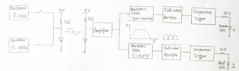
At first, you need know more about every component that will be used in the circuit. One is band pass filter which only make a certain range of signal pass and reduce other unnecessary. These two sites [RC Low Pass Filter and RC High Pass Filter Retrieved from http://hyperphysics.phy-astr.gsu.edu/hbase/electric/filcap2.html] and [Frequency Response and Active Filters Retrieved from http://www.swarthmore.edu/NatSci/echeeve1/Ref/FilterBkgrnd/Filters.html] provide more specific explanations and calculation details to know about high-pass and low-pass filters. They’re trustworthy because they’re from educational website. “Full wave rectifier utilizers both halves of the input sinusoid. To provide a unipolar output, it inverts the negative halves of the sine wave” [Kenneth C.S.]. IR receiver is a strange device but is the most important component which can achieve wireless connection. It is a hardware that can receive signal from an infrared device and then decode to transfer. Here is a link that provides more description about IR receivers. Although this website is business commercial site which is not recommended in academic usage usually, I do suggest it because it can supply information about IR receivers in real life applications, like their types and prices, and these things can really help us in future circuit designing as an electrical engineer.
After being familiar with components you may use in the project, you need plan this circuit. Your instructors and TAs will give you blue print and building directions so I shouldn’t say much more to affect you to make a plan. However, here are two suggests: do your best to avoid or reduce the error; simplify the whole circuits.
Now, I should state what I meet in my building process and give some progress tips. First of all, calculating error can significantly affect the circuit in bad ways. For example, you need set the cutoff frequency point at 1500Hz in a low pass filter so you need a best composition of a certain resistor and capacitor. The formula to calculate this point is fc= 1/2πRC [Kenneth C.S.]. Therefore, you get the result of product of resistor and capacitor which should be 1.06e^-4 and you try your best to find a combination in real resistors and capacitors but there always be an error even it’s truly small. In my opinion, you need replace these impropriate resistors with potentiometers which can change resistance continually by adjusting. In this case, I highly recommend that replace resistors in oscillators with potentiometers. We always think the tiny amount errors can be ignored but in real building process, these errors can lead the whole circuit to failure so potentiometer is a good choice.
Next, connection between each component is another vital problem. After you designed every component, you will find signals are not transferred like you wish in the process of compose. For instance, you will find the strength of the signals sent from the oscillators decrease a lot when you measure the voltage level after the IR receiver. It means during the transferring process, signals become weaker than its original strength and this situation can cause the rest parts won’t work precisely. Therefore we need add an amplifier after the IR receiver to amplify the signal for the following parts. In another case, there are lots of capacitors in this circuit especially in rectifiers and band pass filters. We need prevent the current flowing back after amplifiers so I suggest you can add “buffer” after the amplifier on the receiving board. Because “buffer” is new thing that you didn’t meet before, here is a brief introduction about buffers.
Thirdly, you need keep testing every part after you finish it. Don’t keep building all the time without check its availability. The most confused and frustrated thing is the circuit do not work when its every part is built successfully and you never know what’s happening. So you need get used to test this circuit always right after you finished one component or connect a new component. In my experience, I just check if each single component worked but didn’t usually test the circuit with components together so that when I finished my whole circuit, I didn’t have idea what thing failed and then I need check them again and again to target the incorrect point. It’s definitely frustrated to a beginner.
Finally, I want to talk about building time. As we know, planning is the most important step to access this project. However changing plan during the process also cause the possibility of success. You build the circuit according to the planning chart with calculated data very carefully but there is something wrong all the time even after you check each component again and again. Now, you perhaps need change your mind to a new alternative solution. Because this project is a relatively complicated project, there are always unexpected calculated and system errors which you cannot avoid. And in this situation, continuing putting efforts is like driving to a wrong destination, which is wasting time. The best way to get rid of the system error and obtain the biggest possibility of success is simplifying the circuit.
This project is kind of difficult for beginning students but it can help everyone who is involved in the circuit learning a lot. It’s a summary of what you have learned in electrical engineering and it provides you the first chance to accomplish a real practical project amazingly. In the end, I find some tips about circuits building for you which teach you how to start a project and how to operate the process smoothly. [Tips for Electronics beginners- ratings and working techniques, 2012 Retrieved from http://www.buildcircuit.com/tips-for-electronics-beginners-ratings-and-working-techniques
